
Orignal (shrunk by 1/2) Transformed (shrunk by 1/2)
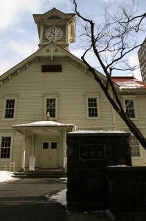
The original image (Sapporo Clock Tower) was taken from here.
Conic anamorphosis is image drawing with shrinking the argument in the polar coordinates in a definite ratio, and the original image appears when we paste it on a cone and view it from the direction of the axis of the cone.
Example.
The original image is stored in an array. For each pixel in the drawing pane, we find the point that should be moved to the pixel, and get the color of the point to determine the color of the pixel.
The constant alpha determines the apex angle.
100 OPTION ARITHMETIC NATIVE
120 LET alpha=1/2*PI              ! apex angle of the cone
130 SET COLOR MODE "NATIVE"       ! enable true color
140 GLOAD "zenkouji.jpg"          ! original image (any of BMP, GIF or JPEG)
150 ASK PIXEL SIZE (1,0;0,1)a,b   ! find the width and length in pixels
160 DIM c(a,b)                    ! prepare an array fitting the size of the image
170 ASK PIXEL ARRAY (0,1) c       ! store the color of points of the image to the array
180 !                               c(1,1) left top, c(a,b) right bottom
190 CLEAR                         ! clear the image
200 SET bitmap SIZE 801, 801      ! re-size the window
210 SET WINDOW -400,400,-400,400  ! re-introduce coordinates
220 SET POINT STYLE 1
230 FOR y=-400 TO 400
240    FOR x=-400 TO 400
250       LET r=SQR(x^2+y^2)*SIN(alpha/2)
260       IF r<>0 THEN LET t=ANGLE(x,y)/SIN(alpha/2)
270       IF ABS(t)<=PI THEN
280          LET i=ROUND(1/2 + a/2 + r*COS(t), 0)  ! left end 1, right end a
290          LET j=ROUND(1/2 + b/2 - r*SIN(t), 0)  ! top end 1, bottom end b
300          IF 1<=i AND i<=a AND 1<=j AND j<=b THEN
310             SET POINT COLOR c(i,j)
320             PLOT POINTS:x,y
330          END IF
340       END IF
350    NEXT x
360 NEXT y
370 END
The following is an exclusive program for apex angle of 60°.
The section of the cone is located at -90°.
100 OPTION ARITHMETIC NATIVE
130 SET COLOR MODE "NATIVE"
140 GLOAD "tokeidai.JPG"
150 ASK PIXEL SIZE (1,0;0,1)a,b
160 DIM c(a,b)
170 ASK PIXEL ARRAY (0,1) c
180 ! c(1,1) left top, c(a,b) right bottom
190 CLEAR
200 SET bitmap SIZE 801, 801
210 SET WINDOW -400,400,-400,400
220 SET POINT STYLE 1
230 FOR y=0 TO 400
240    FOR x=-400 TO 400
250       LET r=SQR(x^2+y^2)/2
260       IF r<>0 THEN LET t=ANGLE(x,y)*2-PI/2
280       LET i=ROUND(1/2 + a/2 + r*COS(t), 0)  ! left end 1, right end a
290       LET j=ROUND(1/2 + b/2 - r*SIN(t), 0)  ! top end 1,bottom end b
300       IF 1<=i AND i<=a AND 1<=j AND j<=b THEN
310          SET POINT COLOR c(i,j)
320          PLOT POINTS:x,y
330       END IF
350    NEXT x
360 NEXT y
370 END
Orignal (shrunk by 1/2) Transformed (shrunk by 1/2)
The original image (Sapporo Clock Tower) was taken from here.
Cylindrical Mirror Anamorphosis is image drawing so that the original image appears when we view the image reflected by a cylindrical mirror. That is drawn by converting the vertical direction of the original to the radius of the polar coordinates and the horizontal direction to the argument of the polar coordinates. But if this conversion is linear, right images shall not appear.
Refer to
How Cylindrical Mirror Anamorphosis Works
We assume a ray radiated from the point of polar coordinate (r,θ) reflects on a cylindrical mirror of radius r0, and reaches the viewpoint on the x-axis distant from the origin by d.
Let the incident angle and reflection angle be α, the angle between the incident light and the radius OP be ψ, the angle between the reflection light and the x-axis be φ.
From the relation between interior angles and exterior angle of a triangle, We have
2α=θ+ψ+φ.
From the sine rule, we have
r:r0:r'=sinα:sinψ:sin(α-ψ)
d:r0:d'=sinα:sinφ:sin(α-φ)
and hence
sinψ=(r0/r)sinα
sinφ=(r0/d)sinα
We find φ from r,θ using above relations.
As we have an approximation α=θ/2 if d,r are large, we ask ψ and φ from α, and hence we ask α from ψ and φ, and ask ψ and φ from α again.
The following program decreases the repetition by using previous ψ and φ for initial values for approximation. (lines 410~450)
The vertical height of the reflection point can be determined by r' and d'.
Note that θ, r', d' are denoted by t,rr and dd respectively in the program.
Example.
Original image is designated in line 120.
The height of viewpoint and the distance from the cylinder are set in lines 170 and 180.
Constants width,height and top in lines 230, 240 and 250 should be adjusted as the accomplished image can be contained.
The radius of the cylinder is set in line 220.
If you decrease the constant 1.00, you must change the lower margin (a in line 190) .
We assume the virtual image appears k times the radius of the cylinder behind of the frontend of the cylinder.
This assumption holds only for the point e times of the radius of the cylinder in front of the frontend of the cylinder.
The value e is determined in line 200.
The value k can be derived from e (line 210).
The value e concerns our perception. Thus e should be adjusted by experiments.
100 OPTION ARITHMETIC NATIVE
110 SET COLOR MODE "NATIVE"
120 GLOAD "tokeidai.JPG"                     ! original image
130 ASK PIXEL SIZE (0,0; 1,1) a,b
140 DIM c(a,b)
150 ASK PIXEL ARRAY (0,1) c                  ! store image into an array
160 CLEAR
170 LET h = b * 5                            ! height of viewpoint
180 LET d = h * 1.2                          ! horizontal distance of the viewpoint from the cylinder
190 LET m = 0                                ! lower margin (inflation of the image position)
200 LET e=((b+m)/a)*(d/h)*2.0
210 LET k=1/(2+1/e)
220 LET r0 =SQR(1/(2*k-k^2))*(a/2)*1.00      ! radius of the cylinder
230 LET width=1200                           ! width if drawing pane
240 LET height=900                           ! height of drawing pane
250 LET top=200                              ! location of the center of the cylinder
260 SET BITMAP SIZE width+1,height+1
270 LET bottom=-height+top
280 SET WINDOW -width/2, width/2, bottom , top
290 DRAW grid(100,100)
300 DRAW circle WITH SCALE(r0)              ! Cylinder
305 PLOT POINTS: 0, -r0*(1*e)               ! The position that is mirroed on the imaginary plane
310 LET d2=d-r0+r0*k                              ! distance to the imaginary plane
320 SET POINT STYLE 1
330 FOR x=-width/2 TO width/2
340    LET phi=0
350    LET psi=0
360    FOR y=bottom TO top
370       LET r=SQR(x^2+y^2)                     ! The absolute of the point
380       IF r>r0 THEN
390          LET t=ANGLE(x,y) +PI/2
400          IF t>PI THEN LET t=t-2*PI           ! Argument of the point (-π~π), downward 0
410          FOR i=1 TO 2
420             LET alpha=(t+psi+phi)/2
430             LET phi=ASIN(r0*SIN(alpha)/d)
440             LET psi=ASIN(r0*SIN(alpha)/r)
450          NEXT i
460          IF ABS(alpha)<=PI/2 THEN
470             WHEN EXCEPTION IN
480                LET rr=r*SIN(alpha-psi)/SIN(alpha)
490                LET dd=d*SIN(alpha-phi)/SIN(alpha)
500             USE
510                LET rr=r-r0
520                LET dd=d-r0
530             END WHEN
540             LET y0=h/(1+dd/rr)
550             LET x0=d2*TAN(phi)                       ! x-coordinate of original image
560             LET y0=h-d2*(h-y0)/(d-r0*COS(alpha-phi)) ! y-coordinate of original image
570             LET i=ROUND(x0+ (a+1)/2,0)               ! array index for x0
580             LET j=b-ROUND(y0-m)                      ! array index for y0
590             IF i>0 AND i<=a AND j>0 AND j<=b THEN
600                SET POINT COLOR c(i,j)
610                PLOT POINTS : x,y
620             END IF
630          END if
640       END if
650    NEXT y
660 NEXT x
670 END
Original (shrunk by 1/4)

Transformed (shrunk by 1/4)
Usage
Accomplished images should be pasted on MS Word or so, printed enlarging as the size of cylinder should become that of the actual cylindrical mirror.